7 Tips You Should Take Account Into For Aluminum Prototype Machining
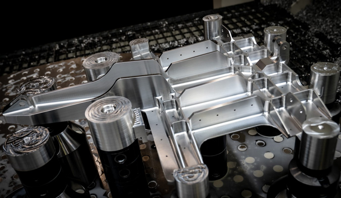
Aluminium is a critical raw element in the industry. Due to its poor hardness and high thermal expansion coefficient, it deforms when machined into thin-walled and thin plate pieces. Along with optimizing tool performance and removing internal tension from the material in preparation, numerous methods may be performed to minimize material deformation.
-
Machined in a symmetrical fashion
It is critical for aluminium components with a high processing capacity to prevent excessive heat concentration from improving heat dissipation and minimizing thermal deformation. The technique for doing this is referred known as symmetrical processing.
Consider the case of a 90 mm thick aluminium plate that has to be cut down to 60 mm thick. Suppose the milling side is instantly switched to the other side since each surface is treated to its ultimate size. In that case, the continuous processing allowance will be significant, resulting in heat concentration and an alloy plate flatness of just 5 mm.
However, suppose the symmetrical processing technique of two sides is repeated. Each surface may be treated at least twice until the final size is achieved, which is beneficial for heat dissipation, and flatness can be adjusted to within 0.3 mm.
-
Stratified multiple machining
When aluminium alloy plate components include several cavities, it is simple for the cavity wall to twist due to the unbalanced stress. The optimal solution is to use a layered multiple processing approaches, which simultaneously processes all cavities.
Rather than completing the component all at once, it might be separated into numerous layers and processed to the appropriate size. The force exerted on the pieces will be more uniform, reducing the likelihood of deformation.
-
Decide on an adequate cutting parameter.
By choosing the right cutting settings, the cutting force and associated heat may be decreased. When cutting parameters are larger than typical during mechanical processing, this results in excessive cutting force, which may easily result in component deformation and impact the spindle’s stiffness and tool durability.
Among all the cutting parameter variables, the amount of back cutting depth has the greatest effect on cutting force. While lowering the number of cutting tools is good for preventing the deformation of components, it also reduces processing efficiency.
This issue may be resolved with numerical control machining’s high-speed milling. By lowering the depth of the back cut, increasing the feed, and raising the machine’s speed, machining may minimize cutting force and ensure processing efficiency.
-
Enhance the capability of cutting tools
Cutting tool material and geometric characteristics significantly affect cutting force and cutting heat. The precise selection of cutting tools and settings is critical for minimizing component deformation during machining.
Geometric characteristics of a tool that may affect performance include the following:
Perspective from the front
The front angle must be adjusted appropriately to maintain blade strength; otherwise, the sharp edge will disappear. Adjusting the front angle may also help prevent cutting distortion, assure smooth chip removal, and lower cutting force and temperature.
The angle at the rear
The rear angle’s size directly influences flank wear and the quality of the machined surface, and cutting thickness is a critical metric to consider while constructing the rear angle. When rough milling, the high feed rate, high cutting load, and high heat generated necessitate that the tool includes heat dissipation. As a result, the rear angle should be reduced. To reduce friction between the machined surface and the machined flank, sharp edges are required in precision milling. Milling should be stable and force-free if the helix angle is big enough.
The angle of primary deflection
Properly lowering the primary deflection angle improves heat dissipation and lowers the processing area’s average temperature.
Enhance the physical appearance of cutting tools
Reduced capacity may be achieved by reducing the number of milling cutter teeth, which is advantageous for processing aluminium alloy. Due to the characteristics of aluminium alloy, cutting deformation is greater, necessitating a big chip storage capacity.
For example, two cutter teeth are utilized with a diameter of less than 20 mm and three cutter teeth in milling cutters with a diameter of 30-60 mm to minimize distortion of thin-walled aluminium alloy components caused by chip blockage.
Cutter teeth grinding with precision
Before using the new blades, carefully grind the front and back edges of the teeth with small oilstones to remove burrs and mild zigzag patterns. Cutting heat may be decreased, but cutting deformation can also be avoided.
Ensure that tool wear is strictly regulated
When tools get worn, the surface roughness of the workpiece rises, the cutting temperature increases and the workpiece deforms. As a result, in addition to choosing tool materials with high wear resistance, the tool wear standard should not exceed 0.2 mm to avoid the formation of nodules. The workpiece’s temperature should not exceed 100 degrees to avoid distortion during cutting.
-
Diverse perspectives
Cutting rough and finishing need distinct procedures. Rough machining entails rapidly removing extra material from the blank surface with the highest cutting speed possible, generating the geometric shape necessary for finishing. The focus is on processing efficiency and material removal rate in this case.
On the other hand, finishing machining needs greater precision and surface quality. Priority should be given to milling quality. The deformation of components may be reduced to some extent when the cutting thickness of the cutter teeth approaches zero.
-
Compression of thin-walled components twice
Clamping force may induce deformation when cutting thin-walled aluminium alloy components. To minimize workpiece deformation by clamping, unclamp the pressed components before completing the final dimension, reducing pressure and returning the parts to their original shape before reapplying pressure.
The second pressing action point is optimal on the supporting surface, and the clamping force should be directed to the highest stiffness. If everything is in order, the compression force should be sufficient to maintain the workpiece’s position without losing it. This procedure needs an expert operator, but it may help decrease distortion of machined components.
-
Drilling and milling
Machining items with cavities brings its own set of challenges. If the milling cutter is placed immediately to the workpiece, the cuts will not be smooth owing to the milling cutter’s inadequate debris space. It results in a buildup of cutting heat, the expansion and distortion of materials, and even the possibility of the part or knife breaking.
The most effective approach for resolving this issue is to pre-drill and then mill. We have extensive expertise in milling aluminium, other metals, and plastics for prototype and production. We hope the information we give is beneficial.