How to Make Impeller Parts by Using CNC machining?
The Impeller of a centrifugal pump is a revolving component that features blades/ vanes rotating/ moving the fluid through it. A shaft connects these vanes or blades. When the impeller rotates, it transforms the energy from a source, such as a motor, into the fluid flow. The impeller is one of the machined parts developed using the CNC machining services. Impellers are an essential feature of a pump because their blades/vanes produce velocity for the fluid. The impeller design determines the pump’s overall efficiency.
Two types of impellers exist:
Axial flow and radial flow impellers are the two primary impeller types. Fluid travels axially to the shaft in an axial impeller. Fluid travels perpendicular to the shaft in a radial flow impeller. Axial impellers are commonly used in multistage split case centrifugal pumps for high flow and low pressure applications. On the other hand, radial impellers are significantly utilized in very low pressure as well as the high flow applications.
- The two types of impellers are open and closed ones. The vanes are then exposed on the open impeller’s further side. The open impeller contains only one shroud. The closed impeller’s vanes are shrouded on both sides. The closed impeller is also known as a double shrouded impeller. Open impellers are only used in single-stage, end suction centrifugal pumps, whereas dual shrouded impellers are utilized in multistage centrifugal pumps with side or top ports.
- Impellers get classed as per the suction type they produce: Liquid reaches the blade’s center from a single direction in a single-suction impeller. A liquid enters the impeller blade’s center from both ends simultaneously in a double-suction impeller. Closed impellers come in single suction and double suction configurations. Steel or stainless steel impellers are commonly used in industrial centrifugal pumps. Some lower-grade pumps are made of brass or bronze, while others are made of plastic.
Because impellers are subjected to various corrosion, erosion, cavitation, and general wear, the impeller material should be carefully evaluated when choosing a pump.
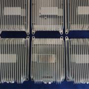
CNC machining services for Impeller
When utilizing a 3-axis CNC machining center for making an impeller, there can be a few major complications, especially for a prototype machining in the beginning ,like the collisions between the impeller and the cutting tool. An impeller’s blade is usually built with a ruled surface. Because the surface gets twisted for attaining the required performance, it might lead to collision and overcutting issues during machining. The Impeller’s hub is normally built with uneven surfaces and machined into a narrow, deep groove. The difficulties of meeting the part’s quality criteria, saving machining time, and avoiding collisions are fundamental difficulties.
By combing the appropriate methods of machining, it creates an integrated machining module of 5-axis for a centrifugal impeller in the form of the CNC machined parts. Cutter location (CL) data are generated because of the hub and blade’s geometric model. Finally, software simulation is used to confirm the CL data. The verification results suggest that the machining process and procedure used are effective.
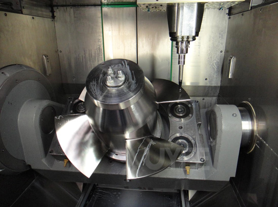
The Impeller is a classic example of five-axis machining.
Modern impeller blades are not as pure in design. They’re frequently created with solid-modeling CAD software, allowing the user to construct intricate shapes while ignoring production efficiency. Majority of the blades are shorter on one end and taller on the other, mainly around the center of the CNC machined parts. Swarf cutting is impossible with modern blades because they must be cut in numerous steps with the nose of a tapered ball nose cutter while the tool axis is controlled to avoid collisions.
Turning impellers from blanks entails roughing off extra material between the blades, semi-finishing the floor and blades, and finally finishing the floor and blades. These operations can be completed in one or potentially two configurations if a multitasking machine is available.
Why use 3+2 machining processes?
Using 3+2 machining processes, it is normal practice to rough out the surplus material between the blades. This is accomplished by indexing the rotating axes, locking them in place to maintain the rigidity of the 5-axis machine, and then attacking the extra exposed material using simple 3-axis toolpaths. This method has the disadvantage of not always removing all of the superfluous material and is thus used by many CNC machining services. It’s tough to keep a record of the material in-process, and there is also a requirement of a cutting overlap, resulting in too many “air” cuts. Furthermore, the space between the blades is frequently deep and narrow, which is problematic because it requires long, slim instruments. Side-cutting is difficult with these tools, especially when the cutting forces continually change, resulting in variable deflection. This generates vibration, reduces tool life, and results in a poor finish.
Modern CAM systems provide a viable option in the form of a 5-axis plunge roughing. In the machine’s stiff 3+2 state, all motions are still carried out. Because cutting pressures are aligned with the cutter’s center axis, tool deflection is negligible, resulting in significantly longer tool life. These toolpaths maintain a track of the material in-process at each stage, and also use “stock recognition” for the toolpaths trimming to the initial stock model, thus reducing the chances of needless air cuts.
The good outcomes
When using a zig-zag cut pattern that starts in the center and extends to the outside perimeter, finishing the floor between the blades is rather simple. This motion keeps the climb-cut constant. A smooth, uniform finish is achieved by extending the entry and departure motions. The tool axis’s center can be forced along a chain kept in between the gap between the blades for the regulation of the tool axis.
The most difficult part is finishing impeller blades. Individual impeller blades are ainly shorter and thinner on one end, and taller on the other, and are also closely spaced. It’s best if the cut pattern stays parallel to the hub surface. To avoid leaving undesired tool markings on the workpiece, it’s also best to cut the entire blade in one continuous stroke.